This is our third post about building a configurable pothole to test autonomous cars. We are making the configurable pothole with five independent Scotch Yoke units controlled by servo motors and an Arduino UNO. For more background, please read the second post of this series where we discuss two methods which convert angular movement to linear movement, why we selected the Scotch Yoke mechanism and why we used the combination of different materials for developing Scotch Yoke units. In this post, we cover how we drive and control Scotch Yoke units using Arduino UNO and servo motors.
NOTE: If you are wondering why anyone would ever bother building a configurable pothole, please read our first blog post.
Interfacing of Arduino with Scotch Yoke Units
To control a up-down movement of Scotch Yoke units, we used a servo motor and an Arduino UNO. The shaft of the servo motor is coupled with a circular wheel of Scotch Yoke unit. So, we can control the movement of the circular wheel by controlling servo motor shaft position which indirectly controls the up-down movement of Scotch Yoke unit.
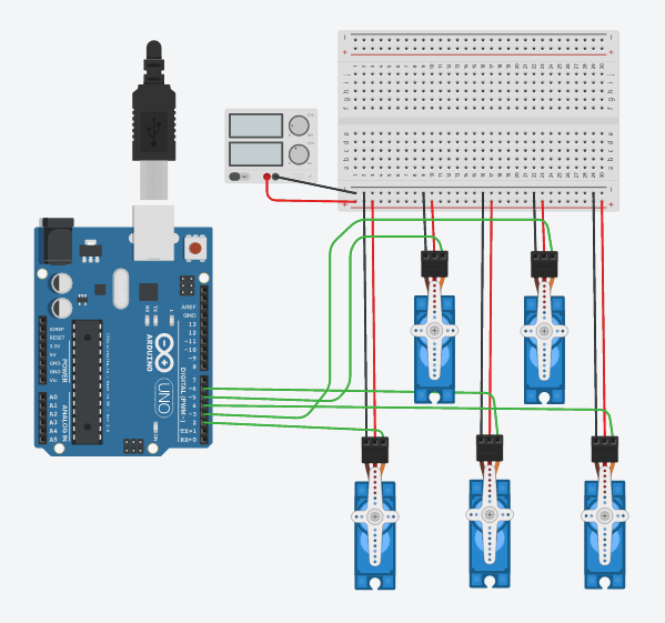
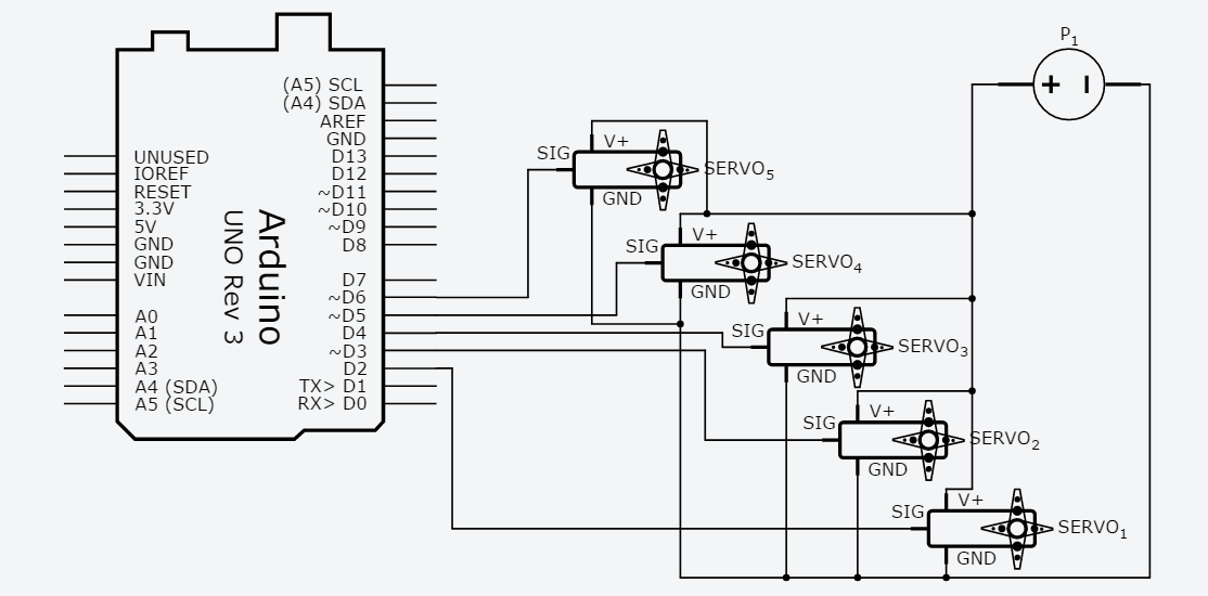
We used five Tower Pro SG-90 servo motors to drive five Scotch Yoke units. The SG-90 servo motor will rotate up to 180 degrees. In our case, 0 to 180 degrees of movement is sufficient to move the platform to lower peak and upper peak. Look at Fig. 1 and Fig. 2 for Lab View and Schematics of the circuit diagram. Signal pin of the five servo Motors is connected to D2 to D6 pins of Arduino UNO. Power pins of the servo motors (+Vcc and GND) are connected to an external 5V 2A DC power supply as the Arduino UNO was not able to drive all the five servo motors. The Arduino UNO was able to drive just two servo motors using its internal/inbuilt power source.
Arduino Code:
/*This is sample code for this blog post. This code does not reflect Qxf2's coding habits*/ #include<servo.h> // create servo object to control a servo Servo servo_1; Servo servo_2; Servo servo_3; Servo servo_4; Servo servo_5; //Declare Variables int target_position = 0; // variable to store the servo position int position_last_set = 0; // variable to store the last servo position int servo_motor_selected = 0; // variable to store selected servo motor number int read_servo_position() { Serial.print("Set servo position(1-179):"); // print msg on monitor for user while(Serial.available()==0) { } // wait here until user enter input data target_position= Serial.parseInt(); // Read integer value entered by user and store it in a varible Serial.println(target_position); if (target_position != 0) { return target_position; } else { return read_servo_position(); } } void setup() { Serial.begin(9600); // Enable serial communication servo_1.attach(2); // attaches the servo on pin 2 to the servo object servo_2.attach(3); // attaches the servo on pin 3 to the servo object servo_3.attach(4); // attaches the servo on pin 4 to the servo object servo_4.attach(5); // attaches the servo on pin 5 to the servo object servo_5.attach(6); // attaches the servo on pin 6 to the servo object } void loop() { Serial.println("Select servo motor by its row and column number(Enter 10 to select all motors): "); while(Serial.available()==0) { } // wait here until user enter input data servo_motor_selected= Serial.parseInt(); // Read integer value entered by user and store it in a varible Serial.print("Selected servo motor:"); Serial.println(servo_motor_selected); switch (servo_motor_selected) { case 11: target_position = read_servo_position(); // Read target position from serial monitor servo_1.write(target_position); // Set servo motor position delay(1000); break; case 12: target_position = read_servo_position(); // Read target position from serial monitor servo_2.write(target_position); // Read target position from serial monitor delay(1000); break; case 13: target_position = read_servo_position(); // Read target position from serial monitor servo_3.write(target_position); // Read target position from serial monitor delay(1000); break; case 21: target_position = read_servo_position(); // Read target position from serial monitor servo_4.write(target_position); // Read target position from serial monitor delay(1000); break; case 22: target_position = read_servo_position(); // Read target position from serial monitor servo_5.write(target_position); // Read target position from serial monitor delay(1000); break; case 10: target_position = read_servo_position(); // Read target position from serial monitor servo_1.write(target_position); // Read target position from serial monitor servo_2.write(target_position); // Read target position from serial monitor servo_3.write(target_position); // Read target position from serial monitor servo_4.write(target_position); // Read target position from serial monitor servo_5.write(target_position); // Read target position from serial monitor delay(1000); break; } } |
Configurable Pothole Setup for testing Autonomous Cars
We used five Scotch Yoke units to design a configurable pothole for testing autonomous car. Look at the GIF shown in Fig. 3 for the configurable pothole setup. With the help of Scotch Yoke units integrated with Arduino UNO and servo motor, we can configure different pothole shapes. We can control depth and width of the pothole by providing different inputs to the Arduino. Look at following Fig. 4 for potholes configured using our prototype. This set of potholes could be the few test cases for testing autonomous cars.

For prototyping purpose, we used Scotch Yoke unit with the thermocol (polystyrene) platform as it is very light in weight and it will be easy for micro servo motor to drive low weight load. But in the case of real testing, we suggest you, to go for pneumatic/hydraulic pistons with a metal platform. As pneumatic/hydraulic pistons are capable of lifting and holding heavy weights. And you can add another layer of tar and sand over a metal platform.
One more important thing about our prototype, our prototype is helpful when you want to test the pothole sensors and pothole sensing algorithms in isolation. The prototype is small enough to fit on a developer’s workbench. The developer can use our prototype for updated their algorithm and get a coarse sense of how the algorithm is performing.
Steps to configure the pothole
By setting multiple Scotch Yoke units, we can configure pothole width and depth as per requirement. Refer following steps to set width and depth of pothole.
- Connect Arduino Uno to your system and open serial monitor available in Arduino IDE
- Select the Scotch Yoke unit which you want to set by entering its number
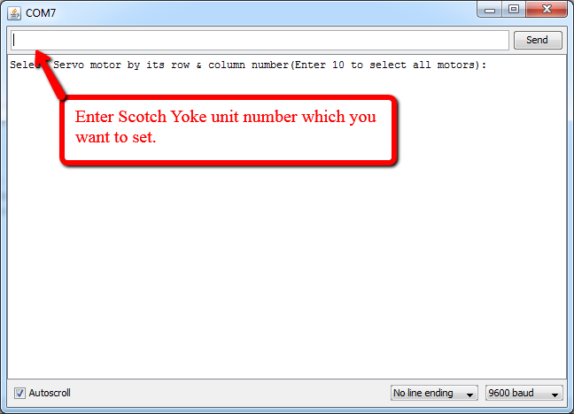

Fig. Select Scotch Yoke unit by entering its number - Set selected Scotch Yoke unit platform position (i.e. depth of a pothole) by assigning value between 1 to 179
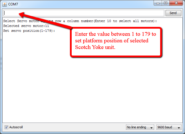
Fig. Set depth of pothole
Steps to set a width of the pothole:
To set a width of the pothole, we need to set a depth of multiple Scotch Yoke units by repeating step 2 and step 3 mentioned above. Look at demo video below where we configured potholes by controlling 5 Scotch Yoke units.
In above video, we showed how easy it is to configure a number of potholes using our configurable pothole prototype. Just a few inputs from Arduino serial monitor and you are all set with a pothole!
I hope you enjoyed following our creative attempt at designing a configurable pothole. If you liked this post, please check out the lessons we learned by implementing this project.
If you are a startup finding it hard to hire technical QA engineers, learn more about Qxf2 Services.

I love technology and learning new things. I explore both hardware and software. I am passionate about robotics and embedded systems which motivate me to develop my software and hardware skills. I have good knowledge of Python, Selenium, Arduino, C and hardware design. I have developed several robots and participated in robotics competitions. I am constantly exploring new test ideas and test tools for software and hardware. At Qxf2, I am working on developing hardware tools for automated tests ala Tapster. Incidentally, I created Qxf2’s first robot. Besides testing, I like playing cricket, badminton and developing embedded gadget for fun.

