Autonomous cars are becoming a reality. We were wondering how testers could contribute to overcoming the engineering challenges related to self-driving cars. In the previous post of series, we discussed how self-driving cars work, typical sensors used in self-driving cars and some unconquered engineering challenges for self-driving cars. At the end of the post, we decided pothole detection was a suitable problem to tackle.
We did not want to go about developing algorithms for pothole detection. Instead, as testers, we wanted to see where testing could help. We figured that developers would want to test their algorithms against a range of pothole sizes and shapes. They would also benefit from having the pothole fit on their workbench so that they can quickly test tweaks and changes to their algorithms and get a quick and dirty indicator of whether their algorithm was ‘sort of working’ or not. So we decided to design and implement a configurable pothole. (And yeah, we got weird looks when we mentioned this to our friends.)
Configurable potholes
To design a configurable pothole, we need to control the vertical movement of some platforms. We know about the pneumatics and hydraulics pistons which are good for up-down movement and are likely being used by the car companies today. But they are very expensive for prototype development. They will also be hard to fit within a development workbench. So we decided to look for alternate mechanisms. We knew motors can be used to power the movement. But motors rotate objects while we needed a linear motion. So we started looking for mechanisms which convert angular moment to a linear movement. We come across two potential solutions: Slider Crank Mechanism and Scotch Yoke Mechanism.
1. Slider Crank Mechanism
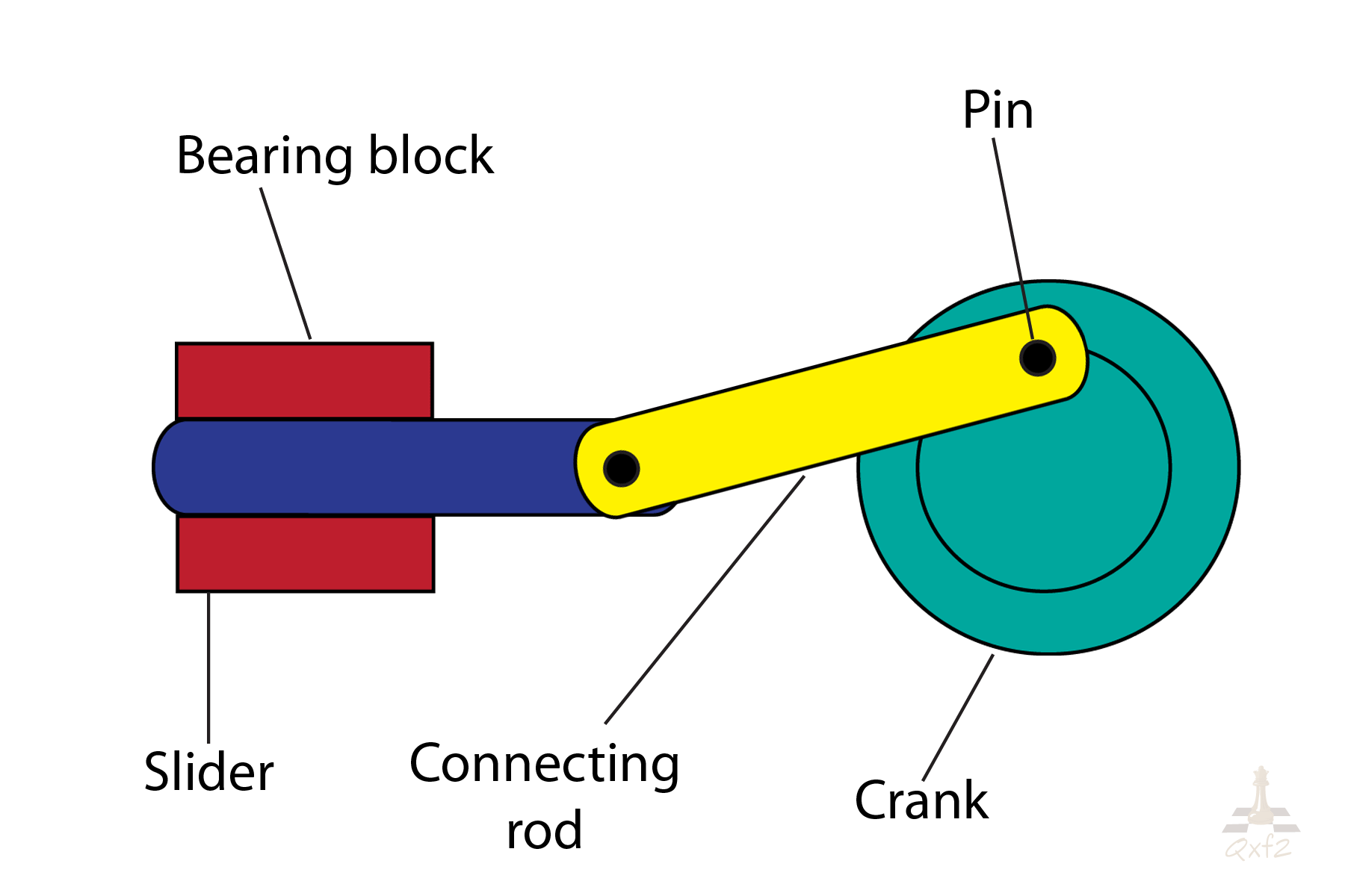
Slider Crank mechanism is shown in Fig 1 converts the rotary motion of a crank to linear motion of a slider and vice versa based on application. Circular wheel/Crank is free to rotate 360 degrees while connecting rod oscillates back and forth as one end of connecting rod attached with circular wheel/crank and another end connected to a slider which restricts it to linear motion. Either crankshaft or slider can be the driver for this mechanism. Click on Fig. 2 to watch the gif of Slider Crack mechanism.
2. Scotch Yoke Mechanism
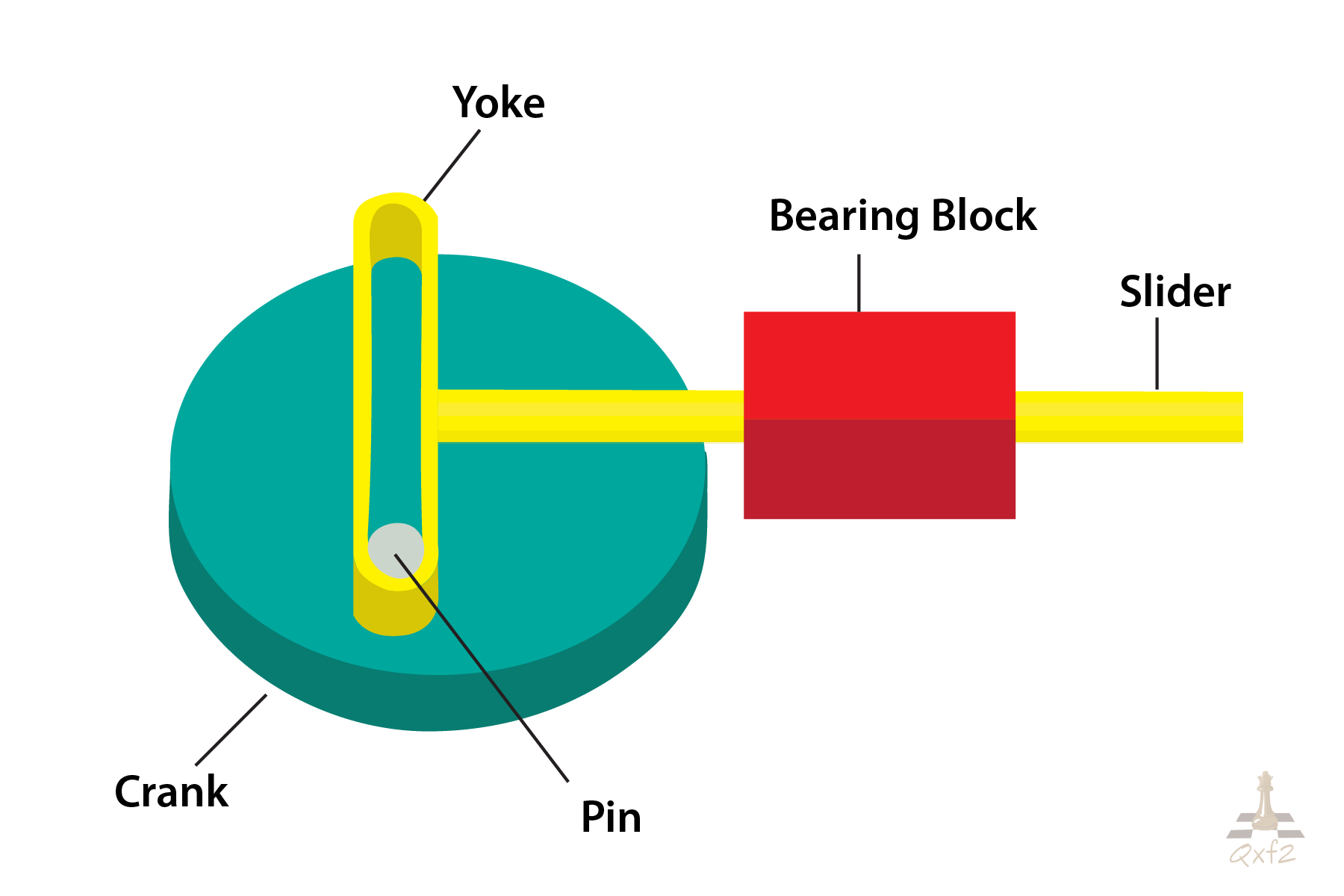
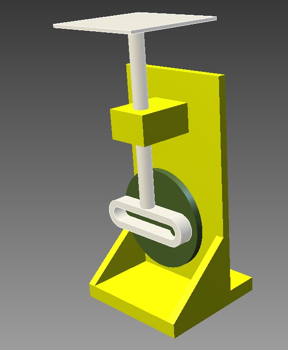
Scotch Yoke Mechanism is one which translates rotary to linear movement or vice versa, by using a pin moving in a slot. Scotch Yoke Mechanism is shown in Fig. 3 converts the rotary motion of a crank to linear motion of a slider and vice versa based on application. The sliding rod is directly coupled to a sliding yoke with a slot that engages a pin on the rotating part. As the wheel starts rotating, it causes the pin to slide inside Yoke which pulls or pushes the Yoke along with sliding rod. Thus, the rotary motion of crack is converted into linear motion of Yoke. Click on fig 4 to watch the gif of Scotch Yoke Mechanism.
Why we selected Scotch Yoke mechanism for our work
Here are a few reasons why we selected the Scotch Yoke mechanism instead of the Slider Crank mechanism:
- Scotch Yoke mechanism produces perfect simple harmonic motion e.g. sine wave where Slider Crank mechanism is unable to produce perfect simple harmonic motion.
- Lesser moving parts which reduce friction in operation.
- Smoother operation
- Delivers more power
Here are a few links that will help you compare the Slider Crank mechanism with the Scotch Yoke mechanism
a) A fun YouTube video
b) A nice demonstration on Wolfram Alpha.
c) A list of advantages that the Scotch Yoke mechanism has over the Slider Crank mechanism.
Scotch Yoke unit design considerations
1. Motor For our application, we decided to drive the crank/rotating wheel using a micro servo motor. Micro servo motor SG-90 has a torque of approx 1.8 kgf.cm.
2. Materials used To keep the weight of the movable part as low as possible, we decided to fabricate movable parts using light weight materials. If we designed the complete model using metal steel, the unit will be very heavy and the micro servo motor will not be able to drive it. So we used a variety of different materials for fabricating our unit. We used aluminum for fabricating the pulley, Yoke frame, and slide bearing block. We used Plyboard for fabricating the circular wheel. Brass was used for fabricating the crank pin and a combination of brass and aluminum was used to provide a smooth sliding operation of the crank pin and yoke frame. We ended up using stainless steel for sliding rod and metal steel for fabricating the base frame. Look at Fig. 5 for our Scotch Yoke unit design. These choices meant we ended up with a decently robust setup while still maintaining a relatively light weight for the parts that needed to be driven by the motor.
3. Dimensions For our configurable pothole prototype, we wanted 50mm of displacement of the platform. The displacement of slider depends on the radius of the crank wheel and position of a crank pin on the wheel. To achieve 50 mm of displacement from Scotch Yoke Mechanism, we need to keep a crank pin on the crank wheel at a radius of 25 mm. To achieve a smooth sliding movement between crank pin and yoke frame, we needed to select crack pin diameter as close as a width of yoke slot.
We outsourced the design and fabrication of our Scotch Yoke unit to Sagar Enterprise. They are very co-operative and good at providing the solutions to our problems. We strongly recommend them!
To know more about how we interfaced Scotch Yoke unit with Arduino and how we used 5 Scotch Yoke units for creating a configurable pothole, refer our next post in this series.
If you are a startup finding it hard to hire technical QA engineers, learn more about Qxf2 Services.

I love technology and learning new things. I explore both hardware and software. I am passionate about robotics and embedded systems which motivate me to develop my software and hardware skills. I have good knowledge of Python, Selenium, Arduino, C and hardware design. I have developed several robots and participated in robotics competitions. I am constantly exploring new test ideas and test tools for software and hardware. At Qxf2, I am working on developing hardware tools for automated tests ala Tapster. Incidentally, I created Qxf2’s first robot. Besides testing, I like playing cricket, badminton and developing embedded gadget for fun.

