This is the first installment of our tutorial series on Arduino. In this tutorial, you will learn about how to build a DC Door Bell and two basic but important modules/functions/commands: Digital Read and Digital Write.
Why this post?
Arduino on a software QA site? Huh? Well, we think the tech world is changing enough that testing will have to adapt. In the not too distant future, knowing how to work with simple circuits will be as common as testers needing to know how to code.
But wait! Even if I buy that reason, what is so special about testers? Can’t they just follow any of the bazillion tutorials online about Arduino? Well, apparently not. Based on our experience, testers learn quickly by doing and exploring rather than following manuals or textbooks. If you look back at how you got good at testing, I am sure you picked up more by actually testing software rather than just reading textbooks.
The material in this series of tutorials has been used to successfully train testers at Qxf2 on hardware. The results were good. So we thought we should share our work on our blog.
Components Required:
- Arduino Board: Arduino is an open-source electronics platform based on easy-to-use hardware and software. Using Arduino, you can read input device/sensors, process the data and control the output devices. For more details refer official site.
- Breadboard: If you are new to Breadboard, refer the link here to know how to use it.
- Jumper Wires: Use to build a circuit
- LED/5VDC Buzzer: Refer the following figure 1 to identify the terminals of LED.
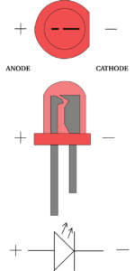

Fig. 1 LED top view, side view, and symbol Take the LED in your hand and look at the LED from the top view. Observe at the outer body structure, you will see a circular body with a cut at one side of the body that looks like ‘-‘ (minus) shape as shown in above Fig. 1 at the top/first image. The terminal near to minus ‘-‘ shape/cut is a cathode (-ve) terminal. You can also identify terminals by looking at the LED from a side view as shown in above Fig. 1 at the middle of the image. Look at the internal structure of LED, the terminal with small kite shape is Anode (+ve) terminal.
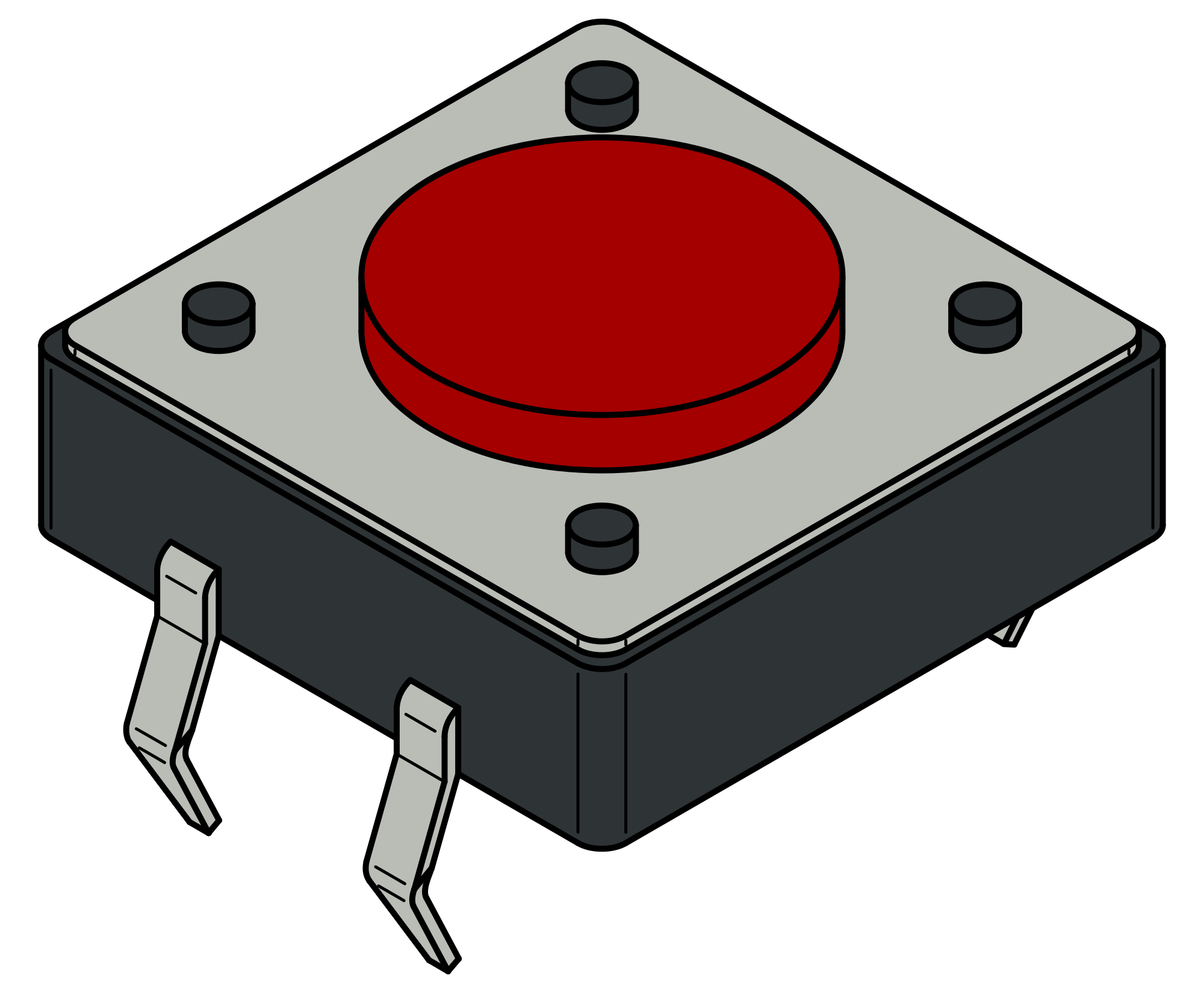
- Push to ON Switch: Fig. 2 shows Push to ON Switch.
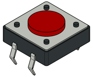
Fig. 2 Push to On Switch This switch is also known as a BED-type switch because of its structure. If you don’t know basics of a switch, please go to the following link here and to know how to identify the terminals of above switch refer the link here.
- Resistor: Here, we require a resistor of 330 ohms or above for a current limiting purpose.

You can get these components fairly easily at many places (including online). We bought our engineers this Arduino super-starter kit.
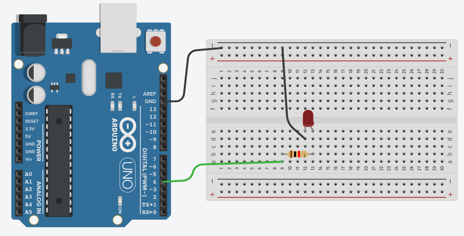
Step 1: Connect LED to digital pin of Arduino:
Pull out all component mentioned above from your kit or from component list of the simulator.
Now, look at the above Fig. 3 and start building a circuit on a breadboard. Here, you need to select any digital pin of Arduino. We selected pin number 4 randomly. Use a jumper wire to connect pin number 4 of the board and any one terminal of the resistor, now connect the second terminal of the resistor to the anode of LED and connect the cathode of LED to GND pin of the board. Refer to Fig. 4 to confirm your connection.
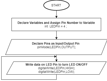
Step 2: Write a code to turn LED ON and OFF:
Refer below flowchart to understand the flow of code.
Note: In below code, we are controlling two LED’s, one which connected to Arduino at pin 4 and other builtin LED which is connected to pin 13. Please read below code line by line. It is very easy to understand.
Arduino Code/Sketch:
//declare a variable and assign pin no. int ledPin = 4; int builtLed= 13; void setup() { // put your setup code here, to run once: pinMode(ledPin,OUTPUT); //set ledPin as a output pin pinMode(builtLed,OUTPUT); //set builtLed as a output pin } void loop() { // put your main code here, to run repeatedly: digitalWrite(ledPin,HIGH); //Turn on external LED digitalWrite(builtLed,LOW); //Turn off built-in LED delay(1000); //add delay of 1 sec digitalWrite(ledPin,LOW); //Turn off external LED digitalWrite(builtLed,HIGH); //Turn on built-in LED delay(1000); //add delay of 1 sec } |
Above code uses a digitalWrite() command/function to turn ON/OFF the LED. When you set a value to HIGH for particular pin using digitalWrite() function, Arduino will set pin value to logic 1 i.e. 5 V and for LOW, it will set pin value to logic 0 i.e. 0 V. So, as per the connection, Arduino turns ON LED when you set pin value of that LED to HIGH and vice-versa.
Now, upload the code/sketch on Arduino Board and observe the inbuilt and external connected LED Blinks alternately. To upload the sketch, you need to follow below steps:
- Open Arduino IDE. Write/Copy the complete code and save it.
- Connect Arduino Board to your system (laptop/desktop)
- Go to Tools Menu > Boards and select your Arduino Board type
- Go to Tools Menu > Port and select the correct port
- Now you are set to upload the code. Click on upload button on the toolbar or Go to Sketch Menu, and click on upload button.
Note: Please do not disturb connection, when you move to step 3 to avoid repetition.
Step 3: Interface switch to Arduino
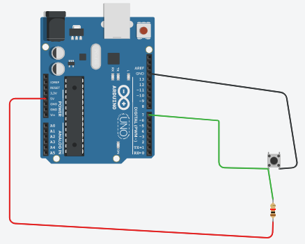
Refer the above Fig. 6 and try to build the circuit on a breadboard. To identify ‘NO'(normally open) pins refer link here. In above connection, we used the resistor to avoid the short circuit between Vcc (5V pin) and GND when we press the switch.
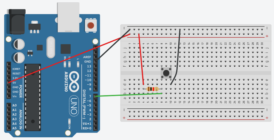
Check out below Fig.7 to confirm your connections are OK or not.
Step 4: Write code to read data on digital pin
Refer below flowchart to understand the flow of code.
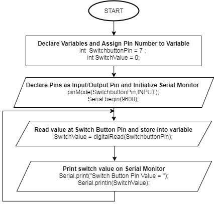
Arduino Code/Sketch:
int switchbuttonPin = 7; //declare a variable and assign pin no. int switchValue = 0; //declare a variable to hold switch value void setup() { // put your setup code here, to run once: pinMode(switchbuttonPin,INPUT); // Set switch button pin as input pin Serial.begin(9600); // Initialize serial monitor } void loop() { // put your main code here, to run repeatedly: switchValue = digitalRead(switchbuttonPin); // read switch value and hold it in variable Serial.print("Switch Value = "); // print message on serial monitor and keep cursor on same line Serial.println(switchValue); // print switch value on serial monitor and move cursor to next line } |
Above code/sketch read the value at pin 7 which is connected to switch. Command/function digitalRead() will help to read the value of any digital pin. As per the switch connection, you will get value ‘0’ at pin 7 of Arduino when we press (and hold) the switch and value ‘1’ in release position because when we press the switch, GND will directly get connected to pin 7 and in normal/release state, pin 7 will get connected to VCC via resistor. You can see these values on serial monitor as we are printing it. Upload the above code/sketch on Arduino and open the serial monitor. To open the serial monitor, you need to click on serial monitor icon available at the upper right corner of IDE or go to tools menu and click on ‘Serial Monitor’ option.
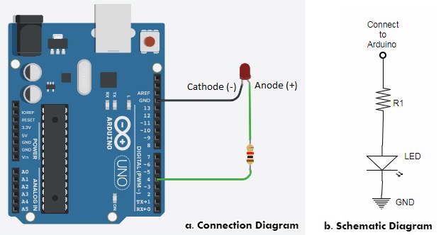
Step 5: Build Door Bell Circuit
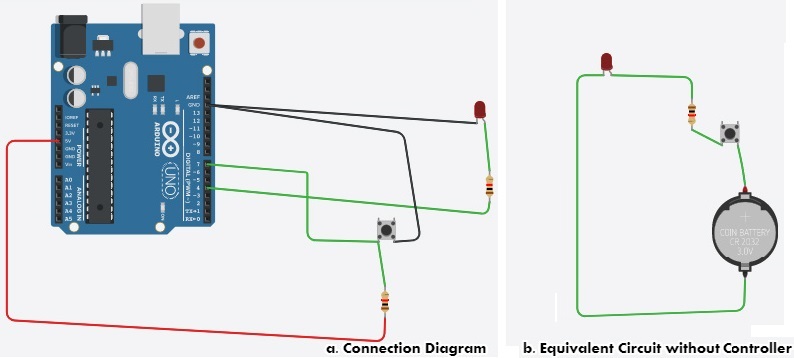
Above connection diagram is a combination of step 1 and step 3 of the tutorial, if you don’t disturb any connection during step 3, your connection will look like above Fig. 9. You can also look at part b of above Fig. 9, it is the equivalent circuit of Door Bell without any controller. You can build that and check it on a breadboard.
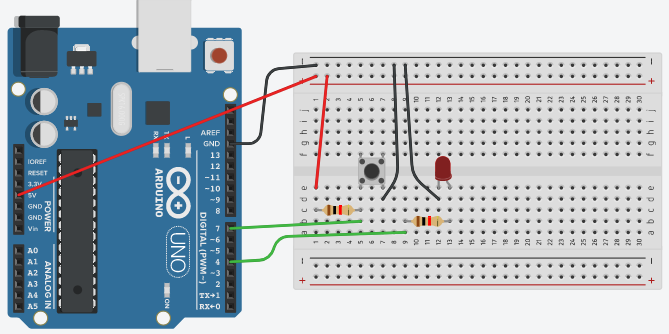
Check out below Fig. 10 for Door Bell Circuit using Breadboard.
Note: After uploading below sketch, if you are able to turn LED ON and OFF by pressing the switch, then you need to replace LED with 5V DC buzzer. Connect +ve terminal of buzzer at the place of Anode and -ve terminal at the place of Cathode.
Step 6: Code for Door Bell
Refer below flowchart to understand the flow of code.
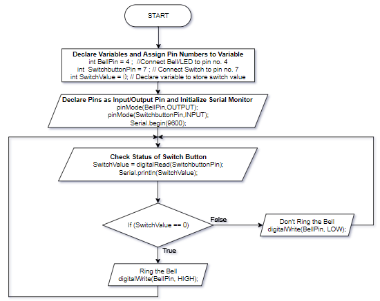
Arduino Code/Sketch:
int BellPin = 4; //declare a variable and assign pin no. int SwitchbuttonPin = 7; //declare a variable and assign pin no. int SwitchValue = 0; //declare a variable to hold switch value void setup() { // put your setup code here, to run once: pinMode(BellPin,OUTPUT); //set Bell Pin as a output pin pinMode(SwitchbuttonPin,INPUT); // Set switch button pin as input pin Serial.begin(9600); // Initialize serial monitor } void loop() { // put your main code here, to run repeatedly SwitchValue = digitalRead(SwitchbuttonPin); // read switch value and hold it in variable Serial.print("Switch Value = "); // print message on serial monitor and keep cursor on same line Serial.println(SwitchValue); // print switch value on serial monitor and move cursor to next line if (SwitchValue == 0) { digitalWrite(BellPin,HIGH); //Ring the bell } else{ digitalWrite(BellPin,LOW); //Keep Bell in off state } delay(500); // add some delay } |
Above code will read the status of the switch using digitalRead command/function and based on the status of the switch it will turn the LED ON/OFF using digitalWrite command/function. Once, the circuit is working fine as expected replace the LED with Buzzer.
Hope you enjoyed the tutorial. In this tutorial, you learned about how to read and write a digital value on Arduino pins. In our next tutorial, you will learn about two more important modules/functions that will help you to control the brightness of a light. If you follow along, at the end of this series, you will distinguish how hardware devices/instruments/products are designed, you can guess how they are programmed, you will get ideas about how to test it and you can build and help others in building products.
Learn more about Qxf2 Services.

I love technology and learning new things. I explore both hardware and software. I am passionate about robotics and embedded systems which motivate me to develop my software and hardware skills. I have good knowledge of Python, Selenium, Arduino, C and hardware design. I have developed several robots and participated in robotics competitions. I am constantly exploring new test ideas and test tools for software and hardware. At Qxf2, I am working on developing hardware tools for automated tests ala Tapster. Incidentally, I created Qxf2’s first robot. Besides testing, I like playing cricket, badminton and developing embedded gadget for fun.


Good explanation