This is the third tutorial of Arduino tutorial series. In this tutorial, you are going to learn about how to interface Servo Motor with Arduino and how to control the movement of Servo Motor from the Serial Monitor.
Background about this tutorial series
We think that testers who get comfortable with hardware are going to have many more testing opportunities open to them. Learning even a little bit of hardware and electronics will make software testers valuable to many companies that have started making smart devices. To that end, we spent time training software testers at Qxf2 on hardware. The results were good. So we thought we should share the training material we used on our blog.
Components Required:
You can get the components listed here fairly easily at many places (including online). We bought our engineers this Arduino super-starter kit.
- Arduino Board
- Jumper Wires
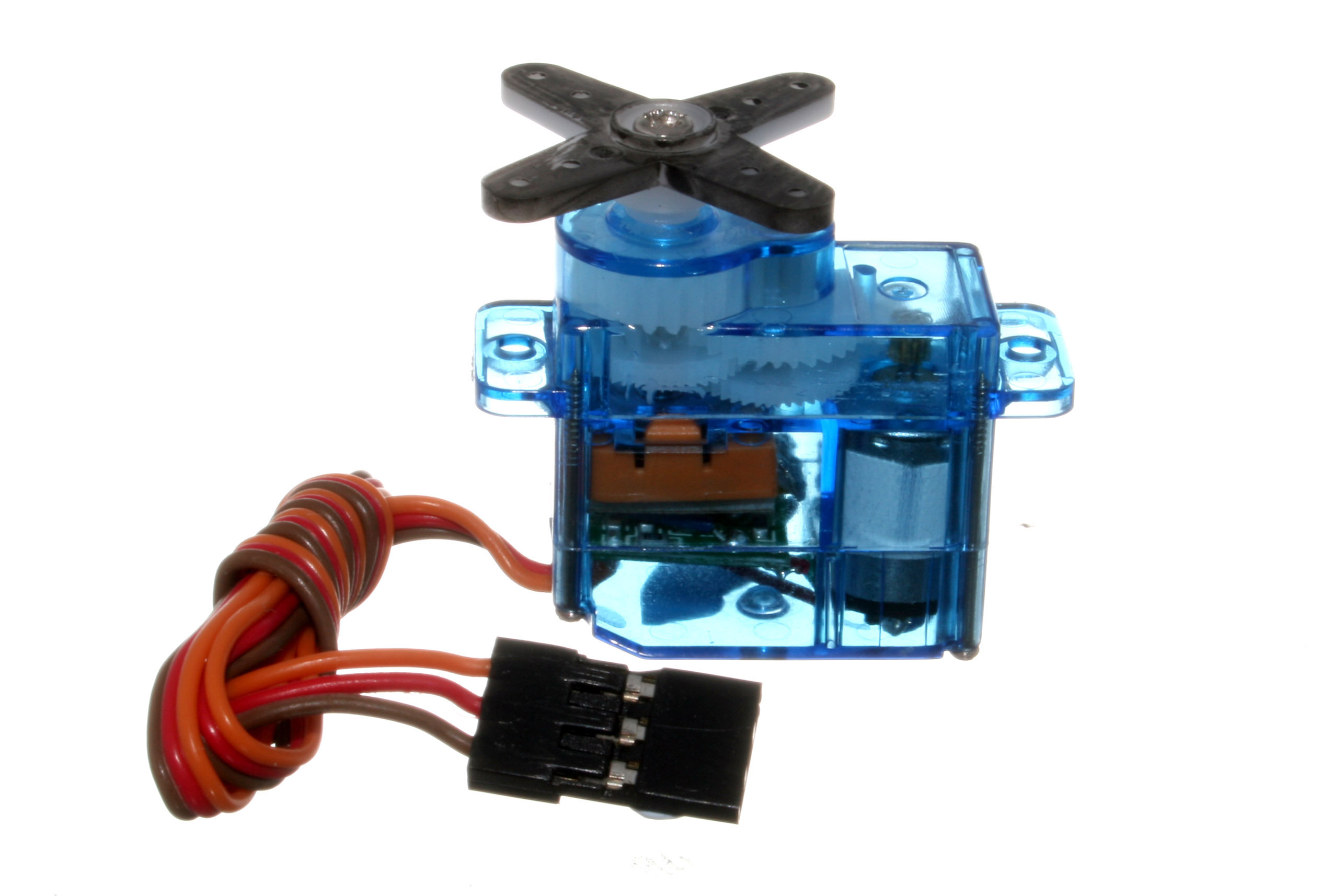
- Servo Motor (In this tutorial, we used micro-servo SG-90)

Fig. 1 Micro-Servo Motor If you are hearing about Servo Motor for the first time, few questions may come to your mind. What is Servo Motor? How does it work? A Servo Motor is a special motor that gives you greater control over how much it rotates.
Technically (you can ignore the rest of this section if you don’t want to get too technical), a Servo Motor is nothing but a simple DC motor with feedback circuitry and comparator/error detector. Here comparator/error detector helps to set the position of Shaft to the required angle. To know more about the construction and working of a servo motor, watch the animated video here.
For this tutorial, we used Micro-Servo SG-90. It rotates approximately 180 degrees. I mentioned approximately because practically, all hobby Micro-Servo Motor will not rotate complete 180 degrees, few of motors vibrate more at higher and lower angle. We need to figure out the angular area of Servo Motor where motor works fine without any vibrations. Note: The reset position of Servo SG-90 is 90 degree (Actually servo moves from +90 degree to -90 degree angle).
Before, moving forward to interface Servo Motor with Arduino Uno. You need to know pinout/wiring details of a Servo Motor.
Pinout/Wiring Details of Micro-Servo Motor:
- Black/Brown Colored Wire = GND Wire
- RED Colored Wire = Vcc Wire
- Orange Colored Wire = Control Signal Wire
For what kind of applications do we need servo motor?
You can use the servo motor in any application where you need an angular/linear moment with velocity and acceleration. Below are the few applications where you can use the servo motor
- In Robotics, for any angular moment (for example, movements of Robotic Arm)
- For Toll Gate
- For Car Wiper
- We used servo motors for our automated pothole testing project to achieve linear movement.
Step 1. Interfacing of Servo Motor with Arduino:
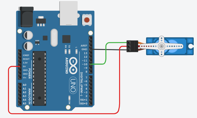
Look at above fig. 2 for interfacing Micro-Servo Motor with Arduino Uno. Here, you need to use a male to male jumper wires for connection. Connect Vcc of Arduino to Vcc of a motor, GND of Arduino to GND of a motor and pin 10 of Arduino to control signal wire of a servo motor.
Step 2. Write a code to control angular movement of the Servo Motor:
Refer below flowchart to understand the flow of code.
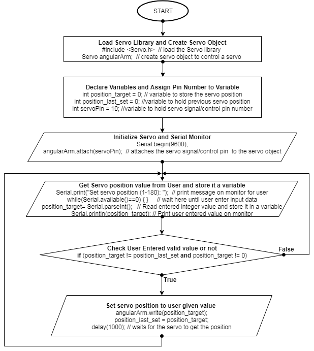
The above flowchart is very helpful to understand the complete code to set Servo Motor position from the serial monitor.
Code:
#include <Servo.h> // load the Servo library Servo angularArm; // create servo object to control a servo int position_target = 0; // variable to store the servo position int position_last_set = 0; //variable to hold previous servo position int servoPin = 10; //variable to hold servo signal/control pin number void setup() { Serial.begin(9600); //Initialize serial monitor angularArm.attach(servoPin); // attaches the servo signal/control pin to the servo object } void loop() { Serial.print("Set servo position (1-180): "); // print message on monitor for user while(Serial.available()==0) { } // wait here until user enter input data position_target= Serial.parseInt(); // Read user entered integer value and store it in a variable Serial.println(position_target); // Print user entered value on monitor if (position_target != position_last_set and position_target != 0) { angularArm.write(position_target); // send control signal to servo motor to take targeted position position_last_set = position_target; // hold servo targeted position in a variable delay(1000); // waits for the servo to get the position } } |
In above code, we used Arduino’s standard Servo library and to know more about this library refer link here. We created a Servo object ‘angularArm’ and attached it to pin number 10 as Servo Motor control wire is connected to pin 10 of Arduino. The script prompts the message on serial monitor for the user to get the targeted position of the Servo Motor. We are looking for targeted servo position angle between (1 to 180). If the user provides the valid targeted position, then above script/code executes servo write function (i.e. angularArm.write(position_target)) to set the position of the Servo Motor.
Note: Here, by using if condition, we are avoiding to set the control signal of the Servo Motor when we get last targeted value and a zero (0) value due to improper settings in the serial monitor. When the user sets serial monitor to a new line or a carriage return or Both NL & CR mode, serial monitor receives zero(0) value and that pulls Servo Motor shaft/rotor angle back to zero.
Upload above code and open the serial monitor, you will see a prompted message on the screen. Provide servo position value between 1 to 180 from serial monitor and check the change in servo shaft position. Provide different servo position value and observe the change in servo shaft position. In the same way, you can figure out the angular area of Servo Motor where motor works fine without any vibrations.
Practice Task:
- Control position of Servo motor using Potentiometer:
- Hint:
- Refer tutorial-2 for potentiometer interfacing with Arduino
- Use Map function to convert POT values to Servo position angle
- Hint:
Hope you enjoyed the tutorial. In this tutorial, you learned about how to interface and control the Servo Motor. Look at our next tutorial here, you will learn about how to interface LCD Display and print user-friendly messages along with the sensors/actuator values. If you follow along, at the end of this series, you will distinguish/understand how the hardware devices/instruments/products are designed, you can also guess how they were programmed, you will get ideas about how to test hardware and you can build and help others in building products.
Learn more about Qxf2 Services.

I love technology and learning new things. I explore both hardware and software. I am passionate about robotics and embedded systems which motivate me to develop my software and hardware skills. I have good knowledge of Python, Selenium, Arduino, C and hardware design. I have developed several robots and participated in robotics competitions. I am constantly exploring new test ideas and test tools for software and hardware. At Qxf2, I am working on developing hardware tools for automated tests ala Tapster. Incidentally, I created Qxf2’s first robot. Besides testing, I like playing cricket, badminton and developing embedded gadget for fun.


Very good, very careful process about this servo motor