In this tutorial, you will learn about how to interface LCD Display with Arduino and display a message on LCD Display. This is the fourth post of our hands-on, Arduino tutorial series. Follow along and you will produce something useful at the end of each tutorial. We also cover just enough electronics theory for you to be able to understand and troubleshoot any problems you may face.
Components Required:
- Arduino Board
- Resistor (330 ohms)
- Potentiometer (10K)
- Jumper wires
- 16×2 LCD Display (HD44780)
Note: You can get these components fairly easily at many places (including online). We bought for our engineers this Arduino super-starter kit.
Pinout Details of LCD Display:
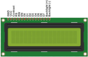
- Vcc and GND: Power to the LCD Display
- Contrast pin (Vo): Control the display contrast
- Register Select (RS) pin: Decides mode of operation (Instruction mode or character mode). To know more about the mode of operation refer link here
- Read/Write (R/W): Selects reading mode or writing mode
- Enable pin (En): Enables writing to the registers
- 8 data pins (D0 -D7): Bi-directional data bus to read and write data
- Backlight (+)and Backlight (-) pins: Turn on/off the LED backlight
Note: LCDs can be controlled in two modes: 4-bit or 8-bit. The 4-bit mode requires seven I/O pins(4 data lines + ctrl signals RS, R/W, En) from the Arduino, while the 8-bit mode requires 11 pins(8 data lines + ctrl signals RS, R/W, En). For this tutorials, we will be using 4-bit mode as we are going to display only the data on LCD and that will require only 7 I/O pins (Indirectly, you can say, we are saving 4 I/O lines for other uses).
Interfacing of LCD Display to Arduino:
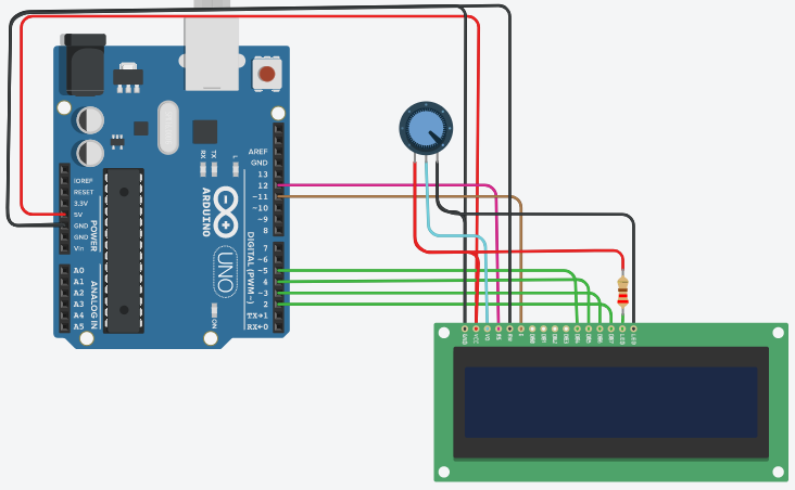
Refer above fig 2 and below wiring details to interface LCD Display with Arduino UNO.
Wiring Details:
- Connect LCD Vcc/Vdd pin to Vcc pin of Arduino
- Connect LCD GND pin to GND pin of Arduino
- Connect LCD RS pin to digital pin 12 of Arduino
- Connect LCD Enable pin to digital pin 11 of Arduino
- Connect LCD R/W pin to GND pin of Arduino because we are going to do ‘write’ action only.
- Connect LCD D4 pin to digital pin 5 of Arduino
- Connect LCD D5 pin to digital pin 4 of Arduino
- Connect LCD D6 pin to digital pin 3 of Arduino
- Connect LCD D7 pin to digital pin 2 of Arduino
- Connect LCD Contrast pin Vo to wiper (pin 2) of 10K POT and connect pin 1 of POT to Vcc and pin 3 to GND
- Connect LCD Backlight(+) pin to Vcc along with current limiting resistor of 220 Ohm
- Connect LCD Backlight(-) pin to GND
Once you are done with the connection, please cross check the connection to confirm all connections are OK or not.
Write a code to display a message on LCD Display:
Code: Please go through below code and comments line by line to understand the code and flow of the complete code.
#include <LiquidCrystal.h> // include the library code /* initialize the library by associating any needed LCD interface pin with the arduino pin number it is connected to */ const int rs = 12, en = 11, d4 = 5, d5 = 4, d6 = 3, d7 = 2; // Declare variables to hold pin numbers LiquidCrystal lcd(rs, en, d4, d5, d6, d7); // Create lcd object to control LCD Display void setup() { // put your setup code here, to run once: lcd.begin(16, 2); // set up the LCD's number of columns and rows: lcd.print("Welcome to"); // Print a message to the LCD. } void loop() { // put your main code here, to run repeatedly: lcd.setCursor(0, 1); //set the cursor to column 0, line 1 (line 1 is the 2nd row, since counting begins with 0) lcd.print("Qxf2 Services"); //Print a message to second line of LCD lcd.noDisplay(); // Turn off the display delay(500); // wait for 500 msec lcd.display(); // Turn on the display delay(500); // wait for 500 msec } |
In above sketch, we used Liquid Crystal Library to control the LCD Display. We created ‘lcd’ object and used begin(), print(), setCursor(), display(), noDisplay() functions to display message and control LCD Display. To know more about the library and supported functions, refer to the link here.
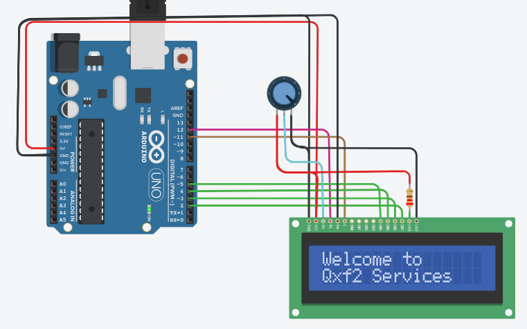
Upload above sketch on your Arduino Uno Board and you can see a message “Welcome to Qxf2 Services” displayed on LCD Screen. Look at below fig. 3 to see how a message will be displayed.
Practice Task:
- Print POT values (any input/sensor values) on LCD Display
- Print the position of Servo Motor on LCD Display
Hope you like the tutorial. In this tutorial, you learned about how to interface with an LCD Display and print messages, sensor or actuator values using Arduino. In our next tutorial here, you will learn about Serial Monitor and how it will make our life easy to print messages along with sensors/actuator values and get values in different data types from a user. If you follow along, at the end of this series, you will distinguish how hardware devices/instruments/products are designed, you can also guess how they were programmed, you will get ideas about how to test hardware and you can build and help others in building products.
Learn more about Qxf2 Services.

I love technology and learning new things. I explore both hardware and software. I am passionate about robotics and embedded systems which motivate me to develop my software and hardware skills. I have good knowledge of Python, Selenium, Arduino, C and hardware design. I have developed several robots and participated in robotics competitions. I am constantly exploring new test ideas and test tools for software and hardware. At Qxf2, I am working on developing hardware tools for automated tests ala Tapster. Incidentally, I created Qxf2’s first robot. Besides testing, I like playing cricket, badminton and developing embedded gadget for fun.

