In this tutorial, you will learn about Ohm’s Law, how to build a Light Dimmer and two important basic modules/commands of Arduino i.e. Analog Read and Analog Write. This is the second installment in Arduino tutorial series. We have designed the series to be hands-on. You will produce something useful at the end of each tutorial. You will also learn just enough electronics and theory to be able to understand and troubleshoot any problems you may face.
Components Required:
Below are the main components required for this tutorial other than Arduino Uno, Breadboard and Jumper Wires:
- Potentiometer (POT): It is a variable type of resistor. You can vary the resistance by rotating the knob of the potentiometer. To know more about internal structure and terminals refer a link here.
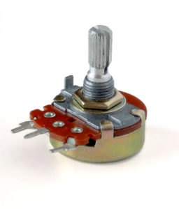
Fig. 1 Potentiometer - LED: Refer the following fig. 2 to identify the terminals of LED
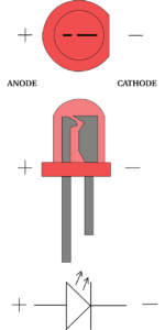

Fig. 2 LED top view, side view, and symbol Take the LED in your hand and look at the LED from the top view. Observe at the outer body structure, you will see a circular body with a cut at one side of the body that looks like ‘-‘ (minus) shape as shown in above Fig. 1 at the top/first image. The terminal near to minus ‘-‘ shape/cut is a cathode (-ve) terminal. You can also identify terminals by looking at the LED from a side view as shown in above Fig. 1 at the middle of the image. Look at the internal structure of LED, the terminal with small kite shape is Anode (+ve) terminal.


Note: You can get these components fairly easily at many places (including online). We bought for our engineers this Arduino super-starter kit.
Ohm’s Law:
It is a very very important law in Electronics. This law is based on the relationship between Voltage(V), Current(I) and Resistance(R).
Mathematical Form of Ohm’s Law:
V = I x R
Based on above equation, you can say,
- If Resistance ‘R’ is constant, then ‘V’ is directly proportional to ‘I’ i.e. if you increase voltage ‘V’, then the current ‘I’ in the circuit will increase proportionally and vice-versa.
- If ‘V’ is constant, then ‘I’ is indirectly proportional to ‘R’. i.e. if you increase the resistance ‘R’ of a circuit, then the current ‘I’ in a circuit will decrease proportionally and vice-versa.
You can practically check the above observations by building a circuit as shown below in fig.3 using a simulator or you can build a physical circuit.
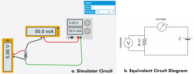
If you are looking for more details about Ohm’s Law refer to the link here.
Now, let’s move on to building Light Dimmer. Pull out all component mentioned above from your kit or from component list of the simulator.
STEP 1: Connect Potentiometer to any analog pin of Arduino
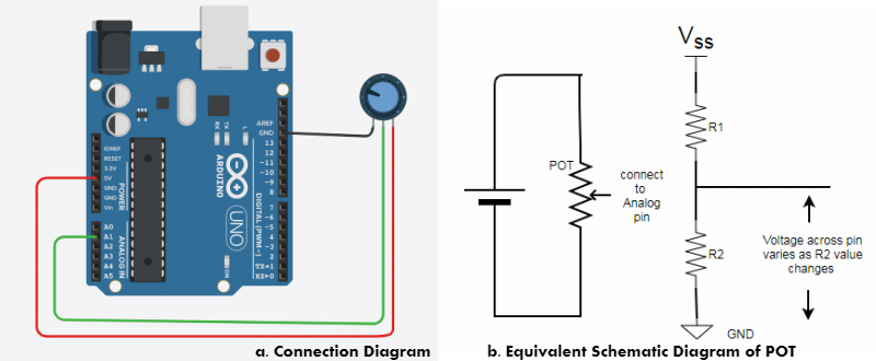
Look at the above fig.4 and start building a circuit on your breadboard/Simulator. Here, you need to select an analog pin of Arduino. We selected pin number A1 randomly. Use a jumper wire to connect pin number A1 of the board and middle terminal of the potentiometer(POT), connect the first terminal of POT to the 5V (Vcc) pin of board and third terminal of POT to GND pin of the board. Now, look at above equivalent schematic diagram of POT, Potentiometer will act as voltage divider circuit. The value of R1 and R2 changes with respect to a change in the position of POT knob. But the value of the total resistor (R1+R2) remains same. So, current(I) in the circuit is same/constant as total resistance is same. Now if you apply Ohm’s law across R1 and R2, you will get the individual voltage drop of ‘I*R1’ and ‘I*R2’ across R1 and R2 respectively. If you see the connection diagram, you will notice, we are measuring the voltage across R2 using pin A1. Arduino Uno has 6 analog pins which consist of 10 bit internal ADC (Analog to Digital Converter). So, the voltage at pin A1 will be converted into 10-bit digital value and the value is between 0 to 1023 in decimal.
Step 2: Write a code to Read Analog Input on Serial Monitor:
Refer below flowchart to understand the flow of code.
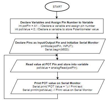
Arduino Code/Sketch:
int potPin = A1 ; //Declare a variable and assign pin number int potValue = 0; //Declare a variable to store POT value void setup(){ // put your setup code here, to run once: pinMode(potPin, INPUT); // Set POT pin as input pin Serial.begin(9600); // Initialize serial monitor } void loop(){ // put your main code here, to run repeatedly: potValue = analogRead(potPin); // Read Analog input and store it in variable Serial.print("POT Value = "); // Print text Serial.println(potValue); // Print value on Serial Monitor delay(100); // Added some delay } |
Above code uses analogRead() command/function to read the analog signal available at pin A1. Arduino Uno board consists of 6 channel 10 bit ADC (Analog to Digital Converters) which converts/maps (0-5)Volts to an integer value (0-1023). For more details about it refer link here.
Upload the above code and check potentiometer value (i.e. the voltage across the analog pin) on Serial Monitor by changing the knob of the potentiometer.
Step 3: Connect LED to any Digital PWM(~) pin of Arduino:
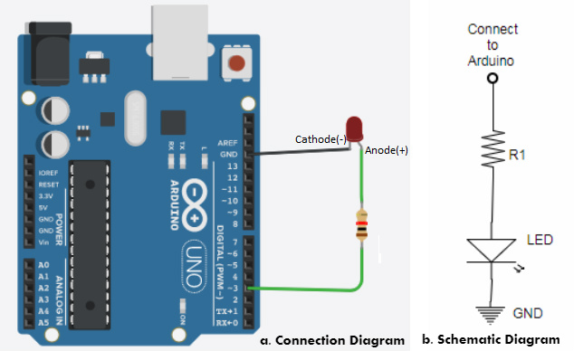
Look at the above fig. 6 and continue building a circuit on a breadboard or simulator without disturbing previous steps connection because we are going to combine both circuits in next step. Here, you need to select any digital PWM(~) pin of Arduino to control the brightness of LED. To know more about the concept of PWM(Pulse Width Modulation) watch a video here. We selected pin number 3. Use a jumper wire to connect pin number 3 of the board and any one terminal of the resistor R1. Connect the second terminal of the resistor R1 to the anode of LED and connect the cathode of LED to GND pin of the board.
Step 4: Write a code to control the brightness of LED:
Refer below flowchart to understand the flow of code.
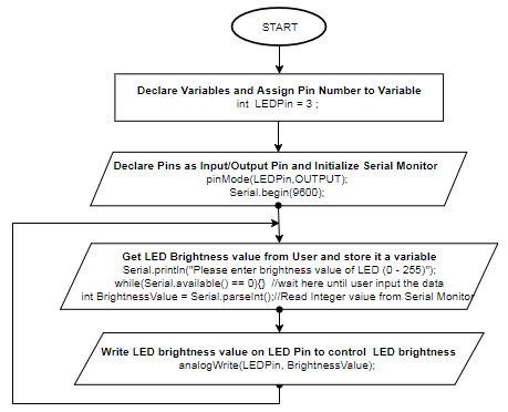
Arduino Sketch/Code:
int LEDPin = 3; //Declare a variable and assign pin number void setup(){ // put your setup code here, to run once: pinMode(LEDPin, OUTPUT); // Set LED pin as output pin Serial.begin(9600); // Initialize serial monitor } void loop(){ // put your main code here, to run repeatedly: Serial.println("Please enter brightness value of LED (0 - 255)"); // promt a message for users while(Serial.available() == 0){} // wait here until user input the data int brightnessValue = Serial.parseInt(); // Read Integer value from Serial Monitor analogWrite(LEDPin, brightnessValue); // Write brightness value on pin to control the brightness of LED delay(1000); // Added Delay of 1 sec } |
Above code will take the brightness value of LED between 0 to 255 from Users and using user-provided brightness value, Arduino controls the brightness of LED. Here, we used AnalogWrite() command/function to write analog value (set PWM wave of required duty cycle) to LED pin.
Note: Only PWM(~) digital pins support Analog Write functionality. For more details refer link here.
Upload the above code, provide any LED brightness value between ‘0’ to ‘255’ from serial monitor and check LED brightness.
Step 5: Build Light Dimmer Circuit
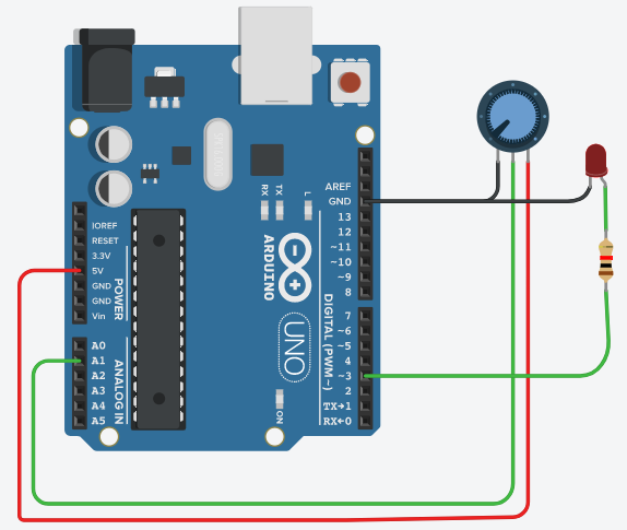
To build the above Light Dimmer Circuit, you just need to combine step 1 and 3. If you have not disturbed your connections during step 3, your circuit will look like the connection diagram shown in above fig.8.
Step 6: Code for Light Dimmer
Refer below flowchart to understand the flow of code.
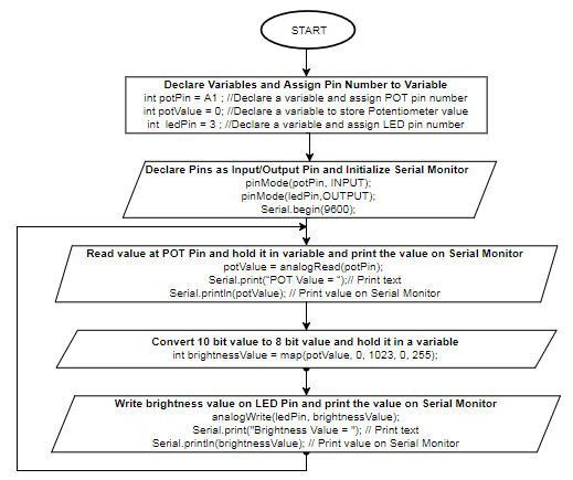
Arduino Sketch/Code:
int potPin = A1 ; //Declare a variable and assign POT pin number int potValue = 0; //Declare a variable to store POT value int ledPin = 3; //Declare a variable and assign LED pin number void setup(){ // put your setup code here, to run once: pinMode(potPin, INPUT); // Set POT pin as input pin pinMode(ledPin, OUTPUT); // Set LED pin as output pin Serial.begin(9600); // Initialize serial monitor } void loop(){ // put your main code here, to run repeatedly: potValue = analogRead(potPin); // Read Analog input and store it in variable Serial.print("POT Value = "); // Print text on Serial Monitor Serial.println(potValue); // Print value on Serial Monitor int brightnessValue = map(potValue, 0, 1023, 0, 255); //Convert value 0-1023 to 0-255 analogWrite(ledPin, brightnessValue); // Set LED brightness Serial.print("Brightness Value = "); // Print text on Serial Monitor Serial.println(brightnessValue); // Print value on Serial Monitor delay(1000); // Added some delay } |
Above code reads the potentiometer value which is connected to pin A1 using analogRead() command/function, stores that value in a variable ‘potValue’ and prints it on the serial monitor for reference purpose. ‘potValue’ which you get from the analogRead() function is of 10-bit, but analogWrite() command/function requires a 8-bit value to set PWM at LED pin 4. So, it is necessary to convert 10-bit value to 8-bit value. You can do the conversion using map() function. To know more about map() function refer to the link here. The converted 8-bit value is stored in a variable ‘brightnessValue’ and then used along with the analogWrite() function to control the brightness of LED.
Upload the above code and check the change in the brightness of LED by varying potentiometer knob.
Hope you enjoyed the tutorial. In this tutorial, you learned about how to read and write analog values on Arduino pins. Look at our next tutorial here, you will learn about how to interface stepper motor with Arduino and controlling the servo position for specific application. If you follow along, at the end of this series, you will distinguish how hardware devices/instruments/products are designed, you can guess how they are programmed, you will get ideas about how to test it and you can build and help others in building products.
Learn more about Qxf2 Services.

I love technology and learning new things. I explore both hardware and software. I am passionate about robotics and embedded systems which motivate me to develop my software and hardware skills. I have good knowledge of Python, Selenium, Arduino, C and hardware design. I have developed several robots and participated in robotics competitions. I am constantly exploring new test ideas and test tools for software and hardware. At Qxf2, I am working on developing hardware tools for automated tests ala Tapster. Incidentally, I created Qxf2’s first robot. Besides testing, I like playing cricket, badminton and developing embedded gadget for fun.


It is cool you can do stuff with arduino.
Hi,
Very nice information, I’ll definitely try this. However, I have a query, Is it possible to use another variable resistor like Rheostat instead of Potentiometer. Before coming here, I was reading an article https://www.derf.com/how-a-variable-resistor-works/ where I got to know about different types of variable resistors but the information is too less to understand. Looking forward to your response.
Hi,
Yes, it will be fine to use any variable resistor here instead of Potentiometer.
Regards,
Rohini