We outline a quick and dirty test for testing Fitbit’s heart rate monitor. This is the first in a series of two posts that will cover our work on developing a cheap and quick test with an acceptable level of accuracy for the Fitbit heart rate monitor.
Why this post?
The ‘why’ behind this post is long. You can safely skip this section if you are not interested.
We think (perhaps is hope a better word?) that hardware and software will soon be tightly coupled in most devices. Most devices will have complex operating systems and the ability to interconnect to other devices over a network. Fitbit, a fitness and activity tracker, is a good pre-cursor of what devices of the future will look like. Software engineers will, most likely, need to start learning at least a little bit about hardware devices too.
Assuming our hunch turns out to be true, testing will have to adapt. At Qxf2, we identified one potential problem that could arise from hardware and software development streams converging – the need for rapid prototyping in hardware.
The development and release cycles for hardware and software are vastly different. Developing software products (most of the time) is much faster than developing hardware products. Hardware products have lesser room for error (you recall instead of patch!) compared to their software counterparts. Hardware is much harder to prototype quickly because the testing and feedback cycle is much longer. This, in turn, means that companies will struggle to bridge the inevitable cultural divide between the hardware and software groups. So, it is possible that the need for rapidly prototyping hardware will be a genuine problem and a problem that testing could mitigate.
Aiding rapid prototyping means that your tests need to be cheap to design, quick to run but need not be very accurate. You can engage in more thorough testing if your prototype passes these ‘acceptance’ level tests. In this post and it’s follow up, we designed cheap and quick tests with acceptable levels of error for the Fitbit heart rate monitor system.
Note 1: I, Arun (founder of Qxf2), understand that we I made several strong and unsubstantiated claims above. I am aware that I could be wrong and/or full of it. If I am wrong, let me know in the comments and I’ll learn and correct myself.
Note 2: The rest of this post is written by Rohan Dudam
About Fitbit
Fitbit is an activity tracker. It is a wireless-enabled, wearable technology device that measures data such as the number of steps walked or climbed, heart rate, quality of sleep, and other personal metrics. We went through many articles about testing accuracy of Fitbit heart rate monitoring system where experts compare ECG results with Fitbit results by having athletes run on treadmills. The final stages of testing need to be thorough, accurate and precise. This kind of testing is time-consuming and costly. Which in turn means that, doing this kind of testing during the prototyping stage slows down the entire process. We think (we are not sure yet) that Fitbit developers are looking for some quick and dirty tests with reasonable accuracy levels during their prototyping stage. And we are trying to fill this hole by looking for some alternatives.
Fitbit heart rate monitoring system:
Fitbit heart rate monitoring system uses an optical heart rate sensor which works on the principle of photoplethysmography (PPG). It is a technique that helps in monitoring the volumetric changes (like change in blood flow) in our body. It uses LEDs and their corresponding sensors as pairs in obtaining information in the form of electrical signals.
When light is incident from the LED on the wrist, a part of the incident light is reflected back from the wrist. A part of incident light is absorbed by the skin, bone, blood vessels etc. As blood flow rate is dynamic, the absorption of light by blood vessels also varies i.e. absorption of light by blood vessels is directly proportional to blood flow rate. Hence, reflected light from the wrist is proportional to the blood flow rate. The reflected light is detected by a detector. The obtained signals are amplified and processed using controllers to give the desired output.
For more details, refer to this link here.
Fitbit heart rate monitoring system: Testing approach:
From the principle of working of the Fitbit heart rate monitor system, it is clear that we can test the Fitbit heart rate sensor by using any light reflecting/refracting material. We tested by using prisms, convex and concave lenses, plastic bottles (yep, really!), cotton cloth, colored paper, etc. Fitbit displayed different heart rate readings for different materials. Take a look at the Fig. 1 below.
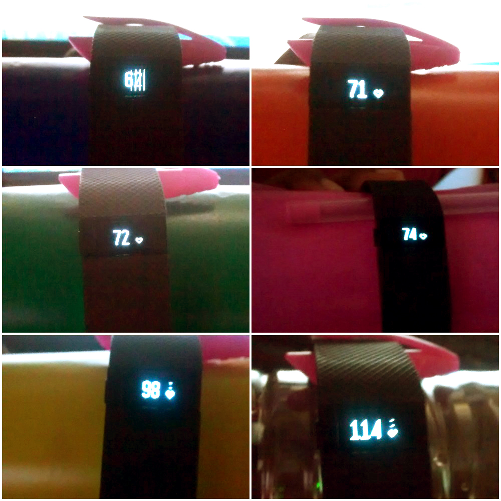
From this experiment, we concluded that heart rate readings depend on the amount of light reflected back from the target. We don’t know about Fitbit’s internal circuitry, specifications, and algorithm used for heart rate monitoring. So that’s challenging. But we are good, resourceful and creative testers. So we decided to test the light detector first and go from there.
1. Fitbit heart rate light detector testing using an external light source:
We tested the light detector by using an external light source controlled by an Arduino Uno.
Test Steps:
1) Cover/ Block heart rate sensor by piece of paper and a thick tape such that it blocks the internal light source
2) Now check heart rate sensor, it will have some baseline, minimum rate. In my case, it was in the range of 60 to 65. This is likely due to the light leakage between internal light source and detector. The LEDs and detector pair are very close to each other making it is very difficult to block the light completely.
3) Design an external light source using LED and Arduino. As per working principle of Fitbit heart rate sensor, the intensity of reflected light will be very less compared to transmitted light from the source, So, here I controlled the intensity of the green led by programming the Uno. I set the on/off time of the led to be 30 msec.
4) Keep the Fitbit heart rate sensor closer to external flashing LED source, and check heart bit rate. The reading starts slowly increasing after some time, say 30 seconds. You can look at the video below to see this happen.
2. Testing the Fitbit heart rate monitoring system as a whole
After testing the light detector alone, we decided to do some integration testing for Fitbit heart rate monitoring system as a whole. I went through many articles related to optical heart sensors and it is little clear to me that, Fitbit uses light modulation and demodulation techniques which were similar to AM, ASK. Like AM demodulation, optical heart rate monitor system separates DC and AC part of reflected light. AC part of reflected light consists of information about heart (pulse) rate and DC part of reflected light consists of steady light due to human skin, bone and mass. DC part of reflected light will be vary for person to person based on their body skin and mass.
Now, its challenge for us to perform controlled and repeated experiments to calibrate Fitbit heart rate readings without using any other standard equipment’s like ECG and without any human involvement in testing e.g. humans running on treadmills.
But at this point, at least I was clear that the heart rate reading totally depends on AC part of reflected light from target. I started thinking about how to vary the AC part of light. I got one idea to mimic blood flow rate of human. According to principle of PPG, heart rate depends on change in reflection of light due to the variation in blood volume in tissues. So we need to vary the amount of reflected light to test heart rate sensor. This is possible by using a band/strip/ribbin of less reflective material and high reflected material. The band/strip/ribbin of paper looks like white black colored bands on zebra body. By controlling speed of moving this band/stripe/ribbin of paper, we can mimic blood flow rate and possibility is high to calibrate it.
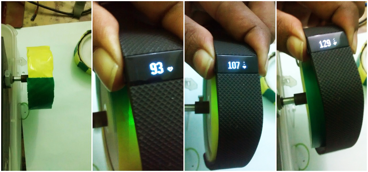
We went ahead and implemented this idea. Look at fig.2 for a sneak peek. To know more about how we implemented this idea, read our next blog post.
If you are a startup finding it hard to hire technical QA engineers, learn more about Qxf2 Services.

I love technology and learning new things. I explore both hardware and software. I am passionate about robotics and embedded systems which motivate me to develop my software and hardware skills. I have good knowledge of Python, Selenium, Arduino, C and hardware design. I have developed several robots and participated in robotics competitions. I am constantly exploring new test ideas and test tools for software and hardware. At Qxf2, I am working on developing hardware tools for automated tests ala Tapster. Incidentally, I created Qxf2’s first robot. Besides testing, I like playing cricket, badminton and developing embedded gadget for fun.


One thought on “%1$s”